Calibration module
Overview
OMG Dosimetry calibration module.
The calibration module computes multichannel calibration curves from scanned films.
Scanned films are automatically detected and selected, or ROIs can be drawn manually.
The lateral scanner response effect (inhomogeneous response of the scanner along the detector array) can be accounted for by creating separate calibration curves for each pixel along the array. This requires exposing long film strips and scanning them perpendicular to the scan direction (see demonstration files). To account for non-flat beam profiles, a text file containing the relative beam profile shape along the film strips can be given as input to correct for non-uniform dose on the film. Alternatively, the lateral scanner response correction can be turned off, then a single calibration curve is computed for all pixels. This simpler calibration is adequate if scanning only small films at a reproducible location on the scanner.
Features:
Automatically loads multiple images in a folder, average multiple copies of same image and stack different scans together.
Automatically detect films position and size, and define ROIs inside these films.
Daily output correction
Beam profile correction
Lateral scanner response correction
Save/Load LUT files
Publish PDF report
Written by Jean-Francois Cabana and Luis Alfonso Olivares Jimenez, copyright 2018 Modified by Peter Truong (CISSSO) Version: 2023-12-06
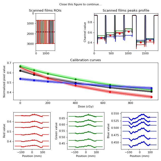
Running the Demo
To run the demo, import the main class and run the demo method:
from omg_dosimetry.calibration import LUT

LUT.run_demo()
(Source code, png, hires.png, pdf)

Usage
This section is used to demonstrate an example for performing gafchromic calibration.
Import LUT and Path
from omg_dosimetry.calibration import LUT
from pathlib import Path
import matplotlib.pyplot as plt
Define the folder containing the scanned tiff images, and the nominal doses [cGy] imparted to the films
Note
Only 16-bit/channel RGB tiff images are supported.
my_path = Path(r"C:/my/folder")
doses = [0.0, 100.0, 200.0, 400.0, 650.0, 950.0]
If you don’t have an image you can load the demo images:
from omg_dosimetry import calibration
my_path = calibration.from_demo_image()
Produce the LUT
lut = LUT(my_path, doses, crop_top_bottom = 650) # Crop needed because an unwanted border
To display films and ROIs used for calibration
lut.plot_roi()
plt.show()
(Source code, png, hires.png, pdf)
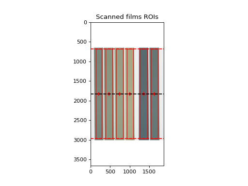
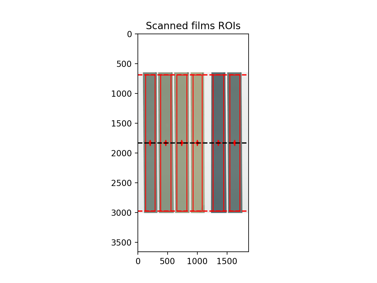

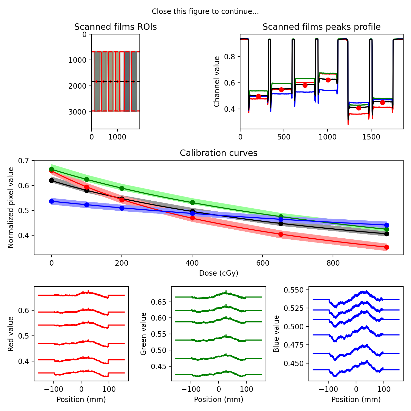
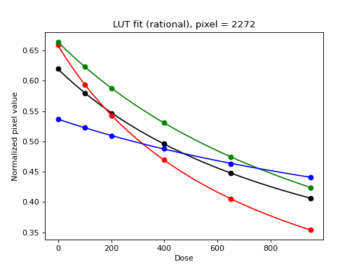
To display a plot of the calibration curve and the fitted algebraic function
lut.plot_fit()
plt.show()
(Source code, png, hires.png, pdf)

Set calibration parameters
For a detalied description see LUT class.
Daily output factor
Daily output factor could be acounted for when films were exposed. Doses will be corrected as doses_corrected = doses * output
from omg_dosimetry import LUT

lut = LUT(..., output = 1)
Lateral correction
Define if lateral scanner response correction is applied.
True: A LUT is computed for every pixel in the scanner lateral direction
False: A single LUT is computed for the scanner.
from omg_dosimetry import LUT

lut = LUT(..., lateral_correction = True)
Beam profile correction
None to not correct for the shape of the dose profile, or path to a text file containing the shape profile (position and relative profile value). Data in the first column should be position, given in mm, with 0 being at center. Second column should be the measured profile relative value [%], normalised to 100 in the center.
from omg_dosimetry import LUT

lut = LUT(..., beam_profile = Path(my_path, "BeamProfile.txt"))
Film detection
Define automatic o manual film detection
lut = LUT(..., film_detect = True)
Crop
If film_detect = True: Number of pixels to crop in the top and bottom of the image. May be required for auto-detection if the glass on the scanner is preventing detection
lut = LUT(..., crop_top_bottom = 650)
ROI size
Define the size of the region of interest over the calibration films. If film_detect = True: ‘auto’ to define the size of the ROIs according to the films, or [width, height] (mm) to define a fixed size.
lut = LUT(..., roi_size = 'auto')
ROI crop
If film_detect = True and roi_size = ‘auto’: Margin size [mm] to apply on each side films to define the ROI.
lut = LUT(..., roi_crop = 3)
Filtering
For image filtering, median filter kernel size to apply on images for noise reduction.
lut = LUT(..., filt = 3)
Metadata
Define general information
info = dict(author = 'Demo Physicist',
            unit = 'Demo Linac',
            film_lot = 'XD_1',
            scanner_id = 'Epson 72000XL',
            date_exposed = '2023-01-24 16h',
            date_scanned = '2023-01-25 16h',
            wait_time = '24 hours',
            notes = 'Transmission mode, @300ppp and 16 bits/channel'
        )

lut = LUT(..., info = info)
API Documentation
LUT class
- class omg_dosimetry.calibration.LUT(path=None, doses=None, output=1.0, lateral_correction=False, beam_profile=None, filt=3, film_detect=True, roi_size='auto', roi_crop=3.0, info=None, crop_top_bottom=None)[source]
Class for performing gafchromic calibration.
- Parameters:
path (str) –
Path to folder containing scanned tif images of calibration films. Multiple scans of the same films should be named (someName)_00x.tif These files will be averaged together to increase SNR.
Files with different basename (‘someName1_00x.tif’, ‘someName2_00x.tif’, …) will be stacked side by side. This is to allow scanning films seperately, either because they don’t fit on the scanner bed all at once, or to have the films scanned at the same location to mitigate scanner response inhomogeneities.
doses (list of floats) – List of nominal doses values that were delivered on the films.
output (float) – Daily output factor when films were exposed. Doses will be corrected as: doses_corr = doses * output
lateral_correction (boolean) –
Define if lateral scanner response correction is applied. True: A LUT is computed for every pixel in the scanner lateral direction False: A single LUT is computed for the scanner.
As currently implemented, lateral correction is performed by exposing long strips of calibration films with a large uniform field. By scanning the strips perpendicular to the scanner direction, a LUT is computed for each pixel in the scanner lateral direction. If this method is used, it is recommended that beam profile correction be applied also, so as to remove the contribution of beam inhomogeneity.
beam_profile (str) –
Full path to beam profile text file that will be used to correct the doses at each pixel position. The text file has to be tab seperated containing the position and relative profile value. First column should be a position, given in mm, with 0 being at center.
Second column should be the measured profile relative value [%], normalised to 100 in the center. Corrected doses are defined as dose_corr(y) = dose * profile(y), where profile(y) is the beam profile, normalized to 100% at beam center axis, which is assumed to be aligned with scanner center.
If set to ‘None’, the beam profile is assumed to be flat.
filt (int (must be odd)) – If filt > 0, a median filter of size (filt,filt) is applied to each channel of the scanned image prior to LUT creation. This feature might affect the automatic detection of film strips if they are not separated by a large enough gap. In this case, you can either use manual ROIs selection, or apply filtering to the LUT during the conversion to dose (see tiff2dose module).
film_detect (boolean) – Define if automatic film position detection is performed. True: The film positions on the image are detected automatically, by finding peaks in the longitudinal and lateral directions. False: The user must manually draw the ROIs over the films.
roi_size (str ('auto') or list of floats ([width, length])) –
Define the size of the region of interest over the calibration films. Used only when film_detect is set ‘auto’.
’auto’: The ROIs are defined automatically by the detected film strips.
[width, length]: Size (in mm) of the ROIs. The ROIs are set to a fixed size at the center of the detected film strips.
roi_crop (float) – Margins [mm] to apply to the detected film to define the ROIs. Used only when both film_detect and roi_size are set to ‘auto’.
crop_top_bottom (float) –
Number of pixels to crop in the top and bottom of the image. Used only when film_detect is set ‘auto’.
May be required for correct detection of films if a glass plate is placed on top of the films and is preventing detection.
info (dictionary) – Used to store information about the calibration that will be shown on the calibration report. key: value pairs must include “author”, “unit”, “film_lot”, “scanner_id”, date_exposed”, “date_scanned”, “wait_time”, “notes”
- lut
When lateral correction is applied:
3D array of size (6, nDoses, nPixel). The first dimension contains [doses, output/profile corrected doses, mean channel, R channel, G channel, B channel]. nDoses is the number of calibration doses used, and nPixel is the number of pixels in the lateral scanner direction.
Without lateral correctoin:
2D array of size (6, nDoses), defined as above, except that a single LUT is stored by taking the median values over the ROIs, instead of one LUT for each scanner pixel.
- Type:
numpy array
- channel_mean
Contains the average RGB value for each dose, at each pixel location.
- Type:
2D array of size (nDoses, nPixel)
- channel_R
Contains the Red channel value for each dose, at each pixel location.
- Type:
2D array of size (nDoses, nPixel)
- channel_G
Contains the Gren channel value for each dose, at each pixel location.
- Type:
2D array of size (nDoses, nPixel)
- channel_B
Contains the Blue channel value for each dose, at each pixel location.
- Type:
2D array of size (nDoses, nPixel)
- doses_corr
Contains the output and beam profile corrected doses, at each pixel location.
- Type:
2D array of size (nDoses, nPixel)
- compute_latpos()[source]
Defines a correspondance pixel -> position (in mm). Center of scanner is defined at y = 0 mm.
- get_longi_profile(size=20, thresh=0.8)[source]
Detect horizontal (x) films position by taking the profile over a small section in the middle of the scanner.
- load_images(path, filt)[source]
Load all images in a folder. Average multiple copies of same image together and stack multiple scans side-by-side.
- plot_calibration_curves(mode='mean', ax=None)[source]
Plots the LUT calibration curves.
- mode: str (‘mean’, ‘all’ or ‘both’)
Defines wether to plot mean curves over all pixels, plot a single curve for each pixel, or both. Only applies when lateral correction is used.
- plot_fit(ax=None, i=None, show_derivative=False, fit_type='rational', k=3, ext=3, s=0)[source]
Plots the fitted function curve.
- show_derivativeboolean
In addition to the function curve, the first derivative of the function is displayed.
- fit_type‘rational’ or ‘spline’
Determines the type of function used for fitting. ‘rational’ : y = -c + b/(x-a) ‘spline’ : Uses the function UnivariateSpline from scipy.interpolate ‘k’, ‘ext’, and ‘s’ are parameters to the UnivariateSpline
- plot_lateral_response(ax=None, filt=0)[source]
Plot the raw scanner response for each channels, as a function of lateral position.
- plot_profile(ax=None)[source]
Plots the scanner profile in the x direction, as used for film detection.
- publish_pdf(filename=None, author=None, unit=None, notes=None, open_file=False)[source]
Publish a PDF report of the calibration. The report includes basic file information, the image and determined ROIs, and the calibration curves
- Parameters:
filename (str) – The path and/or filename to save the PDF report as; must end in “.pdf”.
author (str, optional) – The person who analyzed the image.
unit (str, optional) – The machine unit name or other identifier (e.g. serial number).
notes (str, list of strings, optional) – If a string, adds it as a line of text in the PDf report. If a list of strings, each string item is printed on its own line. Useful for writing multiple sentences.
- static run_demo(film_detect=True, show=True) None[source]
Run the LUT demo by loading the demo images and print results.
- Parameters:
film_detect (bool) – True to attempt automatic film detection, or False to make a manual selection.
show (bools) – Display a summary of the results.